


|
|
Digital Voice HotspotsWARNING! - WORK IN PROGRESS - COMMENTS AND CORRECTIONS WELCOMED! My own notes about configuring the MMDVM_HS_HAT digital voice hotspot using the excellent Pi-Star software and the radios which go through it. This page is really my own notebook, and therefore a work in progress, but I hope it might eventually be a help for others. ResourcesD-Starhttp://www.mdarc.org/activities/repeaters/dstar/linking Configuring the HotspotDisplayI added a 2.4-inch Nextion display based on information in the Pi-Star Wiki. You need to program the display's firmware by downloading a file and copying it to FAT32 formatted micro-SD card. Choose your preferred display format and Nextion size and download from the .TFT files here. There are files for the DB2OE, G4KLX and ON7LDS formats. Although the PD0DIB page connects the display to the RPi, I expect that just the +5 supply is required, but perhaps it's better to terminate the data leads anyway. Once the display is powered up with the card inserted, you will see it updating the firmware. You can then power it down and remove the card. You can connect the display to the MMDVM_HS HAT using the "modem" points. I added in pins so that I could use the wires from the Nextion without cutting off the pre-supplied sockets. Connect 0V and +5 V, and TX to RX reversed (i.e. TX display to RX HAT vice versa). Using the Admin panel with the Pi-Star, select the display as Nextion, and the port as "Modem" as you are using the "modem" connection on the HAT. FrequencyYou need to choose a suitable in-band access frequency. Mine was set to 431.075 MHz, although after careful checking I found that 431.0745 was closer to producing the correct output frequency. Nevertheless, 500 Hz at 431 MHz is not a great error (and the device is in an unheated cupboard). MMDVMHost ConfigurationBased on Pi-Star 3.4.8 ... DMR Mode: Enabled etc. etc. General configurationSetting: DMRSetting: D-Star configurationNeed: Setting: This is simply the reflector setting to start with, and to change reflector see your radio programming. There's a list of reflectors here, which lists REF001C as D-Star's MegaRepeater in London. FusionSettings:
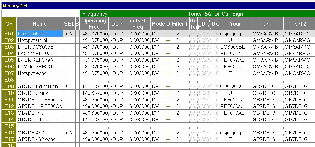
Programming your radio - examplesD-Star - Icom IC-7100Name: Operating Frequency: DUP: Filter: Programming - it's convenient to program a number of channels: Having programmed at least the above, you need to first select a reflector channel you programmed, then press the PTT for about half a second. Then go back to the "talking" channel. Your hotspot should remain connected to the chosen reflector. Listen to check that you are on the expected reflector, and when there is a suitable gap call in. To change reflector, first select the programmed Unlink channel, half-second PTT press, select the desired reflector channel, half-second press, then back to the talking channel. It's actually easier to do than described, once you have the hang of it. This is about the limit of my current knowledge, so comments and corrections are welcome! Here's a screen-shot from the Icom programming software.
DMR - Radioddity GD-77First, add the new channel, then a new zone (optional), to which the new channel is added. To select other reflectors, use the Manual Dial function of the radio. CPS 2.0.5. Why, if my hotspot is set for slot 2, does my GD-77 work with the channel programmed as slot 1?
DMR - Retevis RT3CPS: MD390 Radio Programming Software V1.36 TYT
Fusion - Yaesu FT-70DEYour callsign: CalibrationWhy would you want to calibrate your hotspot? To ensure that your hotspot is on the correct frequency, of course! Others have suggested "tune for minimum BER", but that only matches the error in the hotspot to the error in your own handie-talkie (or whatever). You do require an accurately calibrated receiver, of course, and one which is GPS-locked is strongly recommended. You can check your handie-talkie in a similar way. Stop here if you don't have a calibrated receiver! Calibration is set in the TXOffset and RXOffset values in the Pi-Star Configuration, Expert, MMDVMHost menu option. Looking at the Modem section, you will see TXOffset and RXOffset values you can alter - likely they both will currently be "0". These are approximately the frequency difference you want the hotspot to be from its unmodified frequency, i.e. if the hotspot sends a 433.000 MHz signal 120 Hz high (on 433.000120 MHz), the offsets should be set to -120. Normally, you would set both TXOffset and RXOffset to the same value. MethodI used the MMDVMCal program which is available at github. There is a variant already included in the excellent Pi-Star software which you can run from an SSH shell, and which does all the housekeeping of the Pi-Star services for you. At the command prompt, type pistar-mmdvmcal and then you can list all the commands available by entering the "H" or "h" key. The program allow many different tests, but a plain carrier was what I used, with the commands: "c" to make the hotspot send just a plain carrier, space-bar to turn the carrier on and off, and "q" to exit the program. Note that the program ignores the TXOffset setting the Pi-Star configuration - was unaware of this to start with! NotesI used my GPS-locked receiver to watch the output of the hotspot as the TXOffset was adjusted, and I found that there are very brief bursts of tones at the start or end of each transmission in the different modes which are at the "carrier" frequency of the transmission.
It's obviously a modulated tone, or set of tones, but the central tone is obvious.
Some modes also show a null each side of the carrier (~3 kHz each side as I
recall), and that be used as a coarser guide to correct setting. I observe that the quantisation in the synthesiser is also becoming apparent at the tens of Hz
level - i.e. you might not see the difference between a 119 and a 120 offset
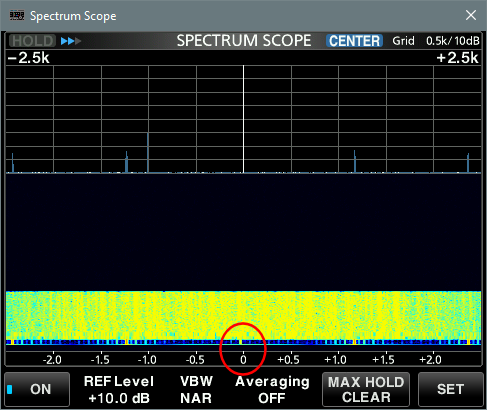
value. An Issue?One issue which I've noticed before and affects at least two of my three hotspots is frequency jumping. Several times I noticed that the frequency of the hotspot would jump ~30Hz lower and then back again, perhaps within a second or two. Later I noticed that on subsequent transmissions either the lower or the higher frequency would be selected, and stay stable throughout someone's over. I suspect this is undesirable behaviour for digital modes, and wonder whether it might be related to the quantisation effect I thought I saw in the synthesiser frequency selection? Screen-shotsHere's an image of the calibration process with a DMR hotspot. Note the
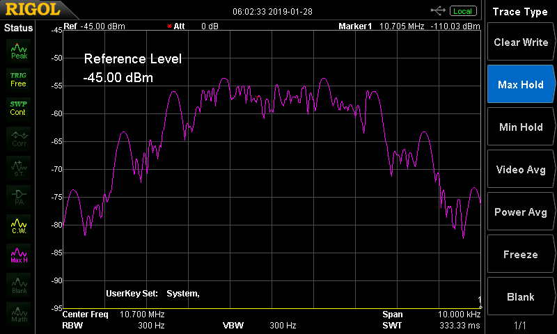
area outlined in Spectrum Analyser ScreenshotsHere are spectrum analyser screenshots which I tried to grab near the start of a transmission to show the tones referenced above. I set the analyser to record peaks to try and emphasise the tones. I would like to have used a narrower resolution bandwidth but that meant a slower scan was needed, and some of the peaks would have been missing. This is unlike SDR/FFT analysis where all frequencies are measured at once, rather than a sweep across the passband in a conventional analyser. Ideally I would have liked some sort of single-sweep facility triggered by the tones, but if that analyser has that facility I don't yet know how to drive it! The initial burst display would otherwise have been much cleaner. All traces are with a 10 kHz span - so 1 kHz/division - looking at the 10.7 MHz IF output from an Icom IC-R8600 on a Rigol DSA-815 spectrum analyser. DMRPeaks at approximately +/- 1.2, 2.4, 3.6 and 4.8 kHz.
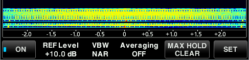
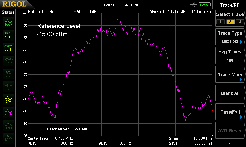
D-StarPeaks at +/- 2.4 kHz and perhaps 4.8 kHz, and a deep notch at ~ +/- 3.5 kHz. More like a sine-wave burst, perhaps, or simply that I caught the burst later and not so much of it?
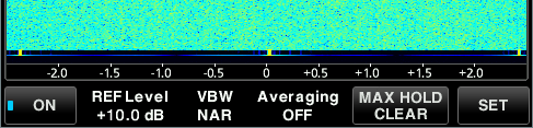
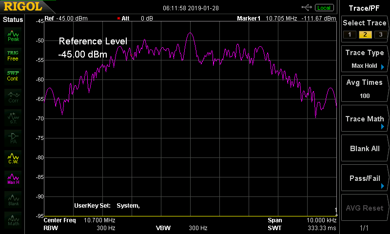
YSFPeaks at +/- 2.4 and 4.8 kHz, but a wider overall bandwidth (less of a drop-off at +/- 5 kHz).
Updating and settings for NTP and SNMPYou may like to use MRTG to monitor things like free memory, CPU usage and CPU temperature. UpdatingTo update the pi-star you use two commands, making the disk writeable before running each. Use PuTTY to log into the RPi from Windows. rpi-rw sudo pistar-update rpi-rw sudo pistar-upgrade SNMP and NTP external accessI found that, by default, the security settings didn't allow SNMP or NTP access from devices on the local network. tp fix this, you need to update the iptables: rpi-rw sudo iptables -I INPUT 3 -s 192.168.0.0/16 -p udp -m udp --dport 123 -j ACCEPT sudo iptables -I INPUT 3 -s 192.168.0.0/16 -p udp -m udp --dport 161 -j ACCEPT rpi-ro Resetting SNMP temporary filesIf you use SNMP "pass" commands, you may find that these stop working once the disk is read-only. To reset that, you can use cron to run a job at e.g. 05:00 every day with the commands: sudo mount -o remount,rw /dev/mmcblk0p2 / sleep 1 sudo rm -rf /var/lib/snmp/.snmp-exec-cache && sudo ln -s /tmp/.snmp-exec-cache /var/lib/snmp/.snmp-exec-cache sleep 1 sudo mount -o remount,ro /dev/mmcblk0p2 / Even then, you will get some breaks in the logging - for
example. |
|
|