RTC
Home Page Up ACARS decoder ADS-B dump1090 AIS receiver Cross-compiling Kernel compile Monitoring NTP RTC Wall Clock Updating GPSD


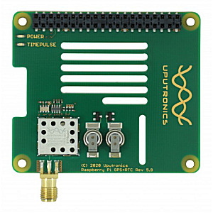
Adding a Real-Time Clock to the Raspberry Pi

This page is heavily based on Uputronics notes and Phil Randal's blog, to whom many thanks.

The board is from Uputronics


Using the Raspberry PiOS

The first step is to enable support for the I2C interface.  You may have already done this for other I2C peripherals:

  • sudo raspi-config
  • Select Interface Options, P5 I2C, and Yes to enable the I2C.  You can now select "Finish".
  • You may be asked to reboot at this point.

If you have not already added the board, do so now.  We can now check that the RTC can be seen by the RPi.

  • sudo apt-get install python-smbus i2c-tools
  • sudo i2cdetect -y 1
pi@RasPi-22:~ $ sudo i2cdetect -y 1
     0  1  2  3  4  5  6  7  8  9  a  b  c  d  e  f
00:          -- -- -- -- -- -- -- -- -- -- -- -- --
10: -- -- -- -- -- -- -- -- -- -- -- -- -- -- -- --
20: -- -- -- -- -- -- -- -- -- -- -- -- -- -- -- --
30: -- -- -- -- -- -- -- -- -- -- -- -- -- -- -- --
40: -- -- 42 -- -- -- -- -- -- -- -- -- -- -- -- --
50: -- -- 52 -- -- -- -- -- -- -- -- -- -- -- -- --
60: -- -- -- -- -- -- -- -- -- -- -- -- -- -- -- --
70: -- -- -- -- -- -- -- --

The RTC (0x52) and GPS (0x42) are both visible on the I2C bus.

The next step is to tell the OS that the device (rv3028) is present on the bus, and what driver to use for that device.

  • Edit the file config.txt
     
  • sudo nano /boot/config.txt
    • add a line: dtoverlay=i2c-rtc,rv3028
       
  • sudo reboot

To check, rerun the i2cdetect command:

pi@RasPi-22:~ $ sudo i2cdetect -y 1
     0  1  2  3  4  5  6  7  8  9  a  b  c  d  e  f
00:          -- -- -- -- -- -- -- -- -- -- -- -- --
10: -- -- -- -- -- -- -- -- -- -- -- -- -- -- -- --
20: -- -- -- -- -- -- -- -- -- -- -- -- -- -- -- --
30: -- -- -- -- -- -- -- -- -- -- -- -- -- -- -- --
40: -- -- 42 -- -- -- -- -- -- -- -- -- -- -- -- --
50: -- -- UU -- -- -- -- -- -- -- -- -- -- -- -- --
60: -- -- -- -- -- -- -- -- -- -- -- -- -- -- -- --
70: -- -- -- -- -- -- -- --

The "52" has been replaced with "UU".

The next steps remove the "fake-hwclock" driver (used by the Raspberry PiOS to guess a starting data and time) to allow the real hwclock (RTC) to work:

  • sudo apt-get -y remove fake-hwclock
  • sudo update-rc.d -f fake-hwclock remove
  • sudo systemctl disable fake-hwclock
  • sudo nano /lib/udev/hwclock-set
  • Comment out five lines, shown here in bold blue on the Edited column.
Before Edited
#!/bin/sh
# Reset the System Clock to UTC if the hardware clock from ...
# was copied by the kernel was in localtime.

dev=$1

if [ -e /run/systemd/system ] ; then
    exit 0
fi

if [ -e /run/udev/hwclock-set ]; then
    exit 0
fi

if [ -f /etc/default/rcS ] ; then
    . /etc/default/rcS
fi

# These defaults are user-overridable in /etc/default/hwclock
BADYEAR=no
HWCLOCKACCESS=yes
HWCLOCKPARS=
HCTOSYS_DEVICE=rtc0
if [ -f /etc/default/hwclock ] ; then
    . /etc/default/hwclock
fi

if [ yes = "$BADYEAR" ] ; then
    /sbin/hwclock --rtc=$dev --systz --badyear
    /sbin/hwclock --rtc=$dev --hctosys --badyear
else
    /sbin/hwclock --rtc=$dev --systz
    /sbin/hwclock --rtc=$dev --hctosys
fi

# Note 'touch' may not be available in initramfs
> /run/udev/hwclock-set
#!/bin/sh
# Reset the System Clock to UTC if the hardware clock from ...
# was copied by the kernel was in localtime.

dev=$1

# if [ -e /run/systemd/system ] ; then
#     exit 0
# fi

if [ -e /run/udev/hwclock-set ]; then
    exit 0
fi

if [ -f /etc/default/rcS ] ; then
    . /etc/default/rcS
fi

# These defaults are user-overridable in /etc/default/hwclock
BADYEAR=no
HWCLOCKACCESS=yes
HWCLOCKPARS=
HCTOSYS_DEVICE=rtc0
if [ -f /etc/default/hwclock ] ; then
    . /etc/default/hwclock
fi

if [ yes = "$BADYEAR" ] ; then
#     /sbin/hwclock --rtc=$dev --systz --badyear
    /sbin/hwclock --rtc=$dev --hctosys --badyear
else
#     /sbin/hwclock --rtc=$dev --systz
    /sbin/hwclock --rtc=$dev --hctosys
fi

# Note 'touch' may not be available in initramfs
> /run/udev/hwclock-set


Commands which should now work:

  • To read time:
    • sudo hwclock -r
       
  • To write time:
    • sudo hwclock -w
       

However...time loss over reboot!

I found that over a power-down reboot, the RTC lost its time, and produced a date sometime around February 2019, almost two years ago.  On querying  this with Uputronics I was pointed straight at the solution on Phil Randal's blog, where he has created a script to set the registers appropriately.  Please see Phil's blog for the details, but here's the script which should be run as root (sudo).  I've extracted these two very long lines for clarity.  Phil notes:

The script I use to configure the rv3028 is from: 

  https://github.com/raspberrypi/linux/issues/2912

Trevor Muraro's comment on 3 April 2020:

  https://github.com/raspberrypi/linux/issues/2912#issuecomment-608193927

That thread and his script should be credited.
 

# Thanks to https://lang-ship.com/reference/Arduino/libraries/RTC_RV-3028-C7_Arduino_Library/class_r_v3028.html#a9cbc9a009d4e5dbfeb29e366140be42b
# And the folks at https://github.com/raspberrypi/linux/issues/2912

#!/bin/bash

function wait_for_EEBusy_done {
   busy=$((0x80))
   while (( busy == 0x80 ))
   do
      status=$( i2cget -y 1 0x52 0x0E )
      busy=$((status & 0x80))
   done
}

rmmod rtc_rv3028

wait_for_EEBusy_done

# disable auto refresh
register=$( i2cget -y 1 0x52 0x0F )
writeback=$((register | 0x08))
i2cset -y 1 0x52 0x0F $writeback

# enable BSM in level switching mode
register=$( i2cget -y 1 0x52 0x37 )
writeback=$((register | 0x0C))
i2cset -y 1 0x52 0x37 $writeback

# update EEPROM
i2cset -y 1 0x52 0x27 0x00
i2cset -y 1 0x52 0x27 0x11

wait_for_EEBusy_done

# reenable auto refresh
register=$( i2cget -y 1 0x52 0x0F )
writeback=$((register & ~0x08))
i2cset -y 1 0x52 0x0F $writeback

wait_for_EEBusy_done

modprobe rtc_rv3028


Update NTP to use the RTC only if required

Now that you have a working RTC you may want to update your NTP so that it works in the absence of the GPS.  Note that the time-of-day accuracy will only be as good as that of the RTC, and of its initial setting.  If possible, get a GPS/PPS setting first.  The RTC super-capacitor battery will likely last a month or more.

You need to tell NTP use use the computer time as a reference-clock, even though it is setting the computer time.  This allows it to provide NTP services to itself or other networked devices.  This will not be UTC, of course, so please be very careful is using this mode.  If other sources become available it will drop using the RTC.

Add these lines to your ntp.conf:

server 127.127.1.0 minpoll 4 maxpoll 4
fudge 127.127.1.0 time1 0.0 refid RTC

Important!

  • Please understand the implications of using this mode before enabling it.  You can use the RTC on its own without using NTP at all.
     
  • This is not UTC, so only sync other clients to an RTC-only server is an isolated system.
     
  • Using type 1 ref-clock driver is purely an emergency/backup mode ONLY when other time sources are not available.  Please read the notes and caveats http://doc.ntp.org/4.1.2/driver1.htm (anything more recent?).
      
  • "In the default mode the behaviour of the clock selection algorithm is modified when this driver is in use. The algorithm is designed so that this driver will never be selected unless no other discipline source is available. This can be overridden with the prefer keyword of the server configuration command, in which case only this driver will be selected for synchronization and all other discipline sources will be ignored. This behaviour is intended for use when an external discipline source controls the system clock. See the Mitigation Rules and the prefer Keyword page for a detailed description of the exact behaviour."
      

RTC drift

To see how the RTC behaves when not disciplined by the OS, I wrote a small program.  Quick and Dirty!  The program is written in Lazarus/FreePascal and gains access to the I2C port using the free TMS-LCL-HW-Pack component.  Only the core I2C access component is required.  In operation, the program polls the RTC "second" byte looking for a change.  When the change is detected the system clock CPU  temperature are read, and recorded to a file for further analysis.  Note that to run this program you need to disable the OS from grabbing hold of the RTC and trying to correct it every 11 minutes.  This is easily achieved by entering:

  sudo rmmod rtc_rv3028

as used in Phil Randal's script above.

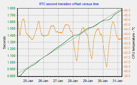
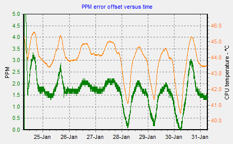
There's also a graphing program I wrote in Delphi 2009, a rather dated Pascal variant now!  You can see that as the RTC is being operated above its turnover temperature (25 °C) it's low in frequency and hence the second transition occurs later and later in time.  From the plots below you can see that the offset rate is greater during the working day - especially on Jan 30 with the sun shining in and heating the room - and lesser during the evening and night when the CPU temperature is lower.  This agrees with the RV-3028 datasheet.  The RPi was unboxed, and mounted vertically to try and improve the airflow across the GPS/RTC board.  The average offset  for the whole period was 0.138 seconds per day, that's 1.59 ppm.


Program: rtcckecker.pas
unit RTCckecker;

{$mode objfpc}{$H+}

interface

uses
  Classes, SysUtils, Forms, Controls, Graphics, Dialogs, StdCtrls, ExtCtrls,
  TAGraph, TMSLCLRaspiHW;

type
  { TFormRTCchecker }
  TFormRTCchecker = class (TForm)
    ButtonClose: TButton;
    ButtonTest: TButton;
    MemoLog: TMemo;
    TimerSample: TTimer;
    procedure ButtonCloseClick (Sender: TObject);
    procedure ButtonTestClick (Sender: TObject);
    procedure FormCreate(Sender: TObject);
    procedure FormDestroy(Sender: TObject);
    procedure FormShow (Sender: TObject);
    procedure TimerSampleTimer(Sender: TObject);
  private
    I2C: TTMSLCLRaspiI2C;
    procedure TakeSample;
  public

  end;

var
  FormRTCchecker: TFormRTCchecker;

implementation

{$R *.lfm}

{ TFormRTCchecker }

procedure TFormRTCchecker.ButtonCloseClick (Sender: TObject);
begin
  Close;
end;

procedure TFormRTCchecker.ButtonTestClick (Sender: TObject);
begin
  TakeSample;
end;

procedure TFormRTCchecker.FormCreate (Sender: TObject);
begin
  I2C := TTMSLCLRaspiI2C.Create (Self);
  I2C.I2CPort := 1;
  I2C.I2CAddress := $52;
  I2C.Open;
end;

procedure TFormRTCchecker.FormDestroy (Sender: TObject);
begin
  I2C.Close;
  I2C.Free;
end;

procedure TFormRTCchecker.FormShow (Sender: TObject);
begin
  MemoLog.Clear;
  MemoLog.Lines.LoadFromFile ('rtc.log');
end;

procedure TFormRTCchecker.TakeSample;
var
  b0, b1: byte;
  t: TDateTime;
  st: string;
  cpu: TStringList;
begin
  b0 := I2C.GetByteRegister (0);
  repeat
    Sleep (1);
    b1 := I2C.GetByteRegister (0);
  until b1 <> b0;
  t := Now;
  st := IntToHex (b1, 2);
  st := st + FormatDateTime ('   yyyy-mm-dd hh:nn:ss.zzz', t);
  try
    cpu := TStringList.Create;
    cpu.LoadFromFile ('/sys/class/thermal/thermal_zone0/temp');
    st := st + Format (' %.3f', [StrToFloat (cpu.Strings [0]) / 1000]);
  finally
    cpu.Free;
  end;
//  ShowMessage (st);
  MemoLog.Lines.Add (st);
end;

procedure TFormRTCchecker.TimerSampleTimer (Sender: TObject);
begin
  TakeSample;
  MemoLog.Lines.SaveToFile ('rtc.log');
end;

end.


Copyright © David Taylor, Edinburgh   Last modified: 2021 Jan 31 at 09:10